BEEK
True Classic
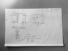
Appreciate the comment from a professional machinist. I am not machinist nor a professional designer. I traced parts on a paper then measured with ruler! We will see what I get when the 3d printed part arrives. then I will make any changes. This was just a napkin drawing!Notes for this drawing..
~Do not use fractions for dimensioning.. they will need to be converted to decimals or mm by the folks making this part.
~Part orientation/views are
Take the time to read this short on drawing views.
https://viva.pressbooks.pub/introegrdesign/chapter/drawings/
~Where is the datum?
~Missing dimensions, missing angle call-outs.
~Do NOT mix mm with fractions or decimal "imperial" dimensions. Use "imperial" decimals or mm.
~Tolerances, tighter the tolerance, more frustration for the folks making this part. Another reasons why fractions are ~Meh~ they do not allow
easy tolerance specifications.. example, 355/113 = ... to how many decimal places?
~Clearances, will it fit for all possible variations of how this part is made and the matching part?
~Use industry standard drills, clearances and related.. Don't "invent" dimensions or holes or threads or ... they cause massive grief unless there is
an extremely valid reasons to deviate from industry standards.
~Material spec.
~Part finish.
~The sharp transition shoulder should be absolutely avoided unless there is a very, very, very good reason for that sharp transition. This is an invitation for a stress riser failure at that transition. Make that a radius large as possible.
~Rounded corners are nice, they add machine time and complexity. If they are not needed, the basic small chamfered corner is easier to make and does not incur the issues with rounded corners.
~~Oh, every mech part drawing must have this note, "Break All Sharp Edges."
~And yes, this part could be done on a Bridgeport or similar manual mill about an hour with modifications for manufacturability and all needed tooling ready.
Keep this video in mind...
Part drawings are legal contracts/documents with details that matter..
Bernice
Luckily the person who is helping me with this also understands my lack of professional drawing. We communicated many times, I even told him I wanted the edges rounded, to not cause stress risers! But i didnt know how to draw it with proper radiuses. He got it! I literally have a large chunk of aluminum on my desk and have contemplated just using a band saw and a drill. I do not have a mill. Even thought about buying one, just to play with. No 3 phase power here! The reality is I could just make it out of 2 pieces of aluminum and bolt it together. But I felt that it would be much nicer to have it as one piece.
Bernice, I see the amazing work you do! I look at it with awe. I can only wish I had your skills. We may have even crossed paths in the past when I was a crew chief on an ARCA car in the early 2000's.
Last edited:


