Rupunzell
Bernice Loui
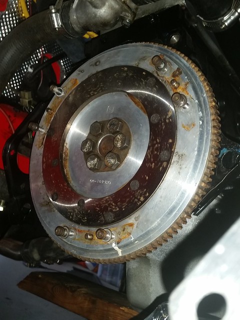
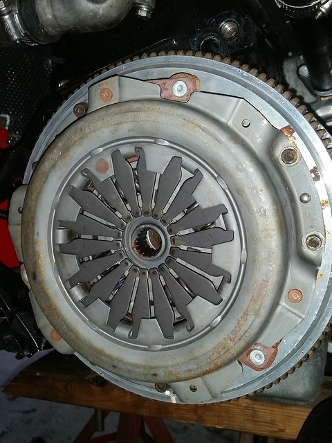
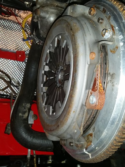
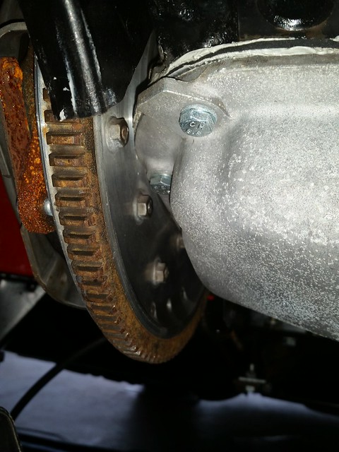
Could be a Tillton Engineering flywheel. Could a picture of the back side of this flywheel be posted?
Tilton engineering flywheels have steel friction faces held in place using aircraft structural screws with flanged lock nuts on the back.
After some discussion with Tilton, I got them to offer Aluminum flywheels for the Fiat SOHC engine with the dowel pin holes, it was based on a sample flywheel sent to them many years ago. Adding the dowel pin holes was a fix for the ability of this Fiat engine to shear off all six M10x1.25 thread, grade 12.9 flywheel bolts under race conditions. After their first one they made and worked out well, Tilton incorporated the dowel pin holes into their standard offering for Fiat.
If this is a Tilton flywheel, know this is a high quality part that is no longer made and rather special.
Bernice
Unknown. I posted an image of the stamped mark on it in this post:
http://www.xwebforums.com/forum/index.php?threads/18618
No amount of searching on the interwebs has helped me find out who made it so far.

")